 TFStudio
 What Angle and Polarization Do to an AR Coating
A coating designed at normal incidence is rarely used there. See what tilt and polarization do to a broadband AR coating, and when it stops working.
Optical coatings vary in transmission and reflection based on the angle of incidence. Lenses see converging beams, beamsplitters sit at 45°, and windows get tilted to keep back-reflections out of the source.
So it is worth asking directly: how far can a coating be tilted before it stops doing its job? This tutorial takes the four-layer broadband AR coating from Refining a Four-Layer Broadband AR Coating and evaluates it at angles it was never designed for.
Nothing here is optimized. This is measurement of an existing design.
The design and conditions
The optimized coating stack layers are specified from the incident medium toward the substrate:
with thicknesses in nanometres.
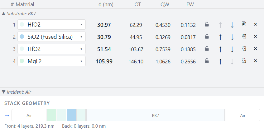
Conditions:
- Incident medium: Air, substrate BK7 (Schott)
- Coated surface: Front, evaluation Ignore other side
- Band: 450–650 nm, the band it was designed for
- Angles: 0°, 15°, 30°, 45°, 60°
Open Analysis → T/R/A. Use the AOI (°) field and the + button to add each angle, and the Curves control to switch between avg, s, and p. Every number below is a band statistic over 450–650 nm on a 2 nm grid.
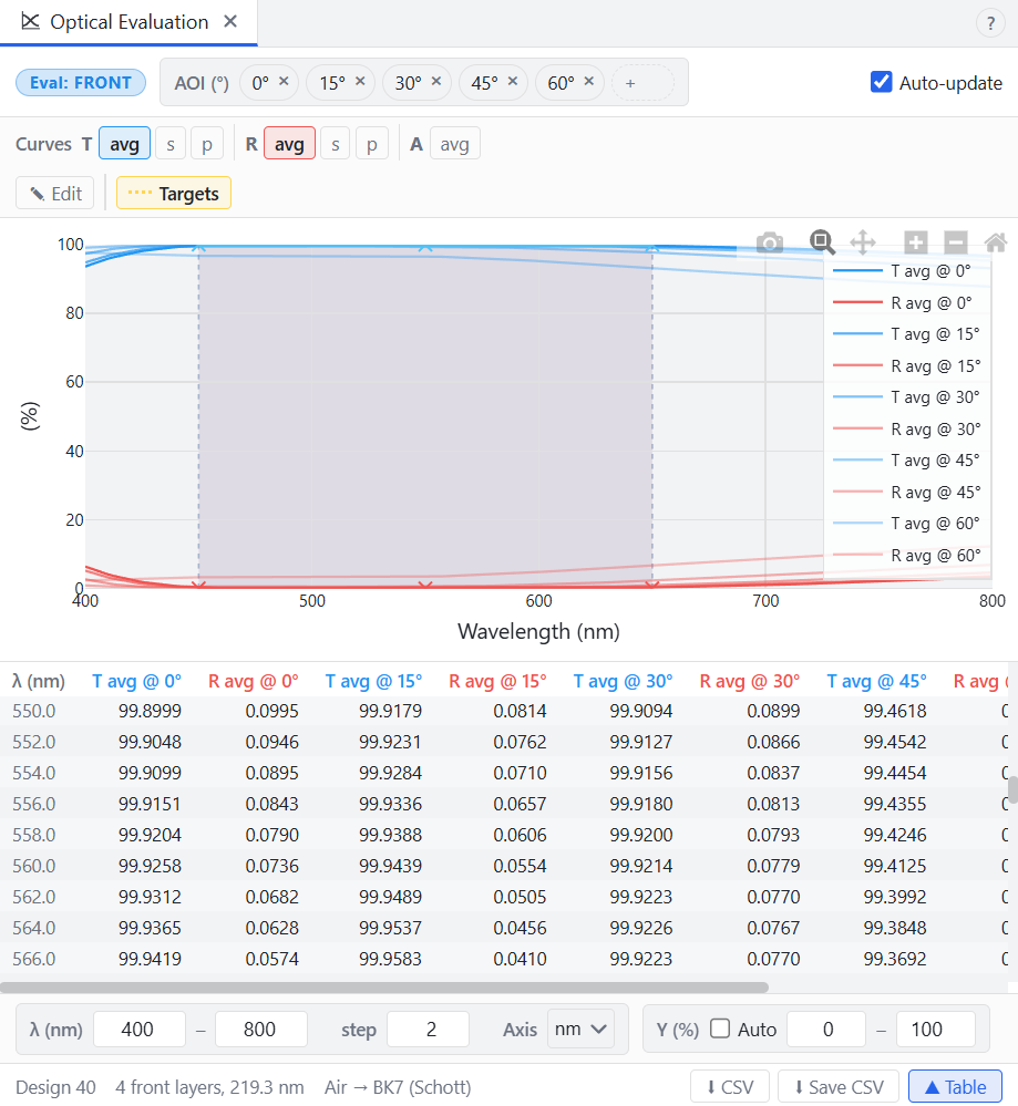
Reflectance against angle
| AOI | Average | Worst in band |
|---|---|---|
| 0° | 0.0792% | 0.2858% |
| 15° | 0.0874% | 0.3645% |
| 30° | 0.2098% | 0.8409% |
| 45° | 0.8798% | 2.2699% |
| 60° | 4.0282% | 6.8092% |
The degradation is not proportional to angle. It is negligible to 15°, roughly 2.6× at 30°, 11× at 45°, and 51× at 60°.
The practical reading of that table: a coating specified at normal incidence is usually safe in an cone or a few degrees of mount tilt, and is not safe at 45°. The common assumption that usually "a few degrees will not matter" happens to be true.
A useful reference point for the far end: uncoated BK7 reflects 4.2448% on average in this band at normal incidence. At 60° the coated surface reflects 4.0282%. Tilting the part to 60° gives back essentially the entire benefit of coating it, since the coated surface is then no better than bare glass would have been if you had left it untilted. The coating is still doing work at 60°: bare glass at 60° reflects 9.2315%. It is just no longer winning against the baseline that mattered.
Why the spectrum moves
There is a shift toward shorter wavelengths. The phase thickness of a layer at oblique incidence is
where is the propagation angle inside the layer. The factor means the layers behave as though they were thinner, so every spectral feature moves to a shorter wavelength.
The reflectance minimum near 475 nm at normal incidence sits at 469 nm at 15° and 452 nm at 30°.
s- and p-polarization
The second effect is polarization splitting. At non-normal incidence, s- and p-polarized light see different admittances.
| AOI | Average | Average | Worst | Worst |
|---|---|---|---|---|
| 0° | 0.0792% | 0.0792% | 0.2858% | 0.2858% |
| 15° | 0.1014% | 0.0734% | 0.3717% | 0.3573% |
| 30° | 0.2894% | 0.1301% | 0.9606% | 0.7212% |
| 45° | 1.2387% | 0.5210% | 3.1364% | 1.4033% |
| 60° | 5.4482% | 2.6081% | 10.4759% | 3.1545% |
The s-polarized reflectance is always the worse of the two, and it degrades faster. At 60° the average curve reads 4.03%, but the s-polarized component averages 5.45% and peaks at 10.48% at 650 nm, more than three times the p-polarized value of 3.14% at the same wavelength.
If your source is polarized, or if there is a polarizing element anywhere downstream, the averaged curve is the wrong number to design against.
Design considerations
At 60°, p-polarized light reflects 2.6081% from the coated surface, and only 0.154% from bare, uncoated BK7.
For p-polarization at this angle, the antireflection coating is roughly seventeen times worse than no coating at all.
That can be explained with Brewster's angle for BK7, which is about 56.7°, so at 60° an uncoated glass surface is already nearly perfect for p-polarized light; there is essentially nothing left to antireflect. The coating, optimized for a condition 60° away, can only add reflection to a surface that had already solved the problem by itself.
The general lesson is the one worth carrying: a coating is a solution to a stated problem, and outside that statement it carries no guarantee at all, not even the guarantee of being better than nothing.
Wavelength-angle map
Curves at five chosen angles answer five specific questions. They do not show the shape of the problem, because the angle axis is sampled five times and the eye has to interpolate between separate lines.
Plot Engine can be used to plot wavelength and AOI against trasmittance or reflectance.

Open Analysis → Plot Engine and switch the sidebar to 3D Surface. Then:
- Select 3D Surface.
- Under Quantity (Z), choose T, with Polarization
avgand Surfacefront. - Set the X axis to Wavelength, from 400 to 800, with 81 steps (5 nm grid).
- Set the Y axis to AOI, from 0 to 70, with 71 steps (one point per degree).
- Under Appearance, choose Heatmap and the Jet colorscale.
- Click ▶ Compute surface.
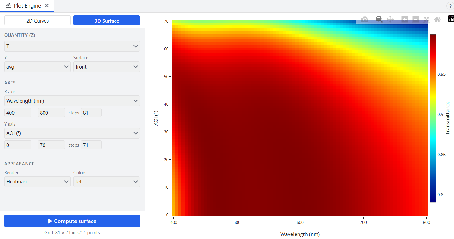
Two things are visible at once:
- The high-transmittance region leans left. Its features drift toward shorter wavelengths as angle increases.
- Band narrows. The band is widest along the bottom edge of the map and closes in as it rises.
What to do about it
Optimize coatings specifically for their intended operational angles. If the coating will be used at 45°, put 45° in the merit function. The merit function targets can be configured for a single specific angle or multiple discrete angles.