 TFStudio
 Building a Quarter-Wave Dielectric Mirror
Learn the basic HL-pair structure of a dielectric mirror, build an eight-pair 550 nm mirror with Stack Formula, and see what the pair count changes.
A basic dielectric mirror is one of the simplest multilayer coatings. It uses alternating layers with high and low refractive index. In coating notation, these materials are called H and L.
This tutorial builds an eight-pair mirror for 550 nm with TFStudio's Stack Formula tool.
What an HL pair does
Each layer is one quarter-wave optical thickness at the design wavelength :
At normal incidence, the reflections from the interfaces in an alternating quarter-wave stack add constructively around . Repeating the pair raises the reflectance:
The letters describe optical roles, not fixed materials:
- H is the material with the higher refractive index.
- L is the material with the lower refractive index.
- A bare
HorLin Stack Formula means one quarter-wave optical thickness.
More pairs increase the reflectance in the high-reflectance band. The index contrast between H and L largely determines the width of that band.
Build the mirror with Stack Formula
Open Design → Formula.

Enter this formula:
(HL)^8
Set the controls as follows:
- Set Reference λ₀ (nm) to 550.
- Assign
Hto built-inTiO2. - Assign
Lto built-inSiO2 (Fused Silica). - Set the incident medium to
Air. - Set the substrate to
BK7 (Schott). - Set Apply to to Front.
- Leave Start from substrate unchecked.
- Click New design.
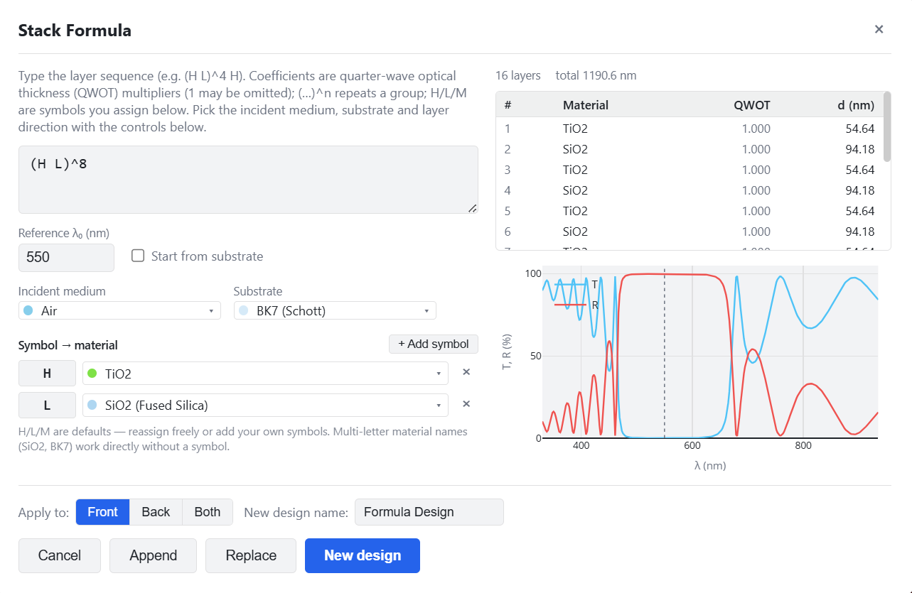
The parentheses group one HL pair, ^8 repeats it eight times, and TFStudio
converts every quarter-wave optical thickness into a physical thickness using
the selected material data at 550 nm.
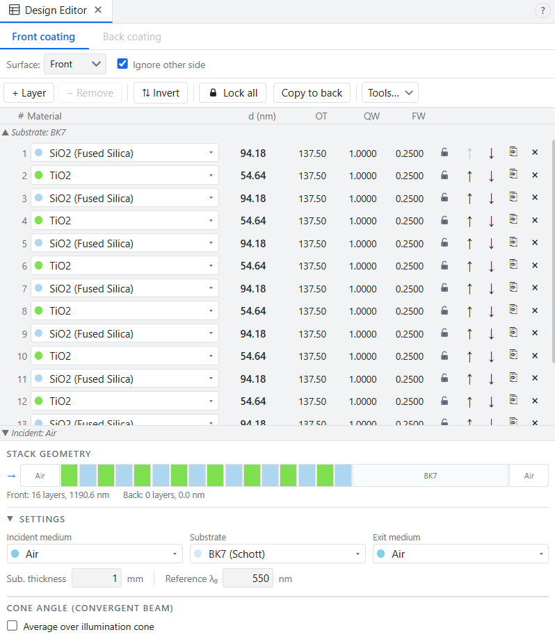
The result contains 16 layers. The formula is written from the incident medium toward the substrate. The Design Editor displays the substrate-adjacent layer first, so its table appears in the reverse direction.
Check the result
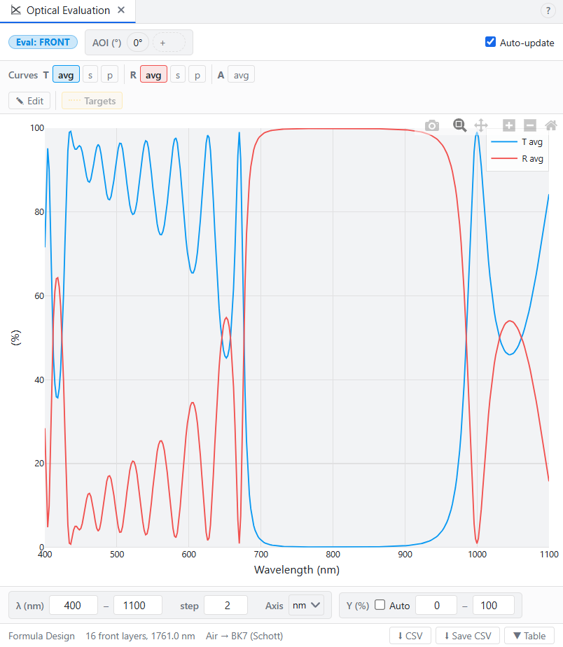
Open the Optical Evaluation window (Analysis → T/R/A). The reflectance curve should show a high-reflectance band centered near the design wavelength.
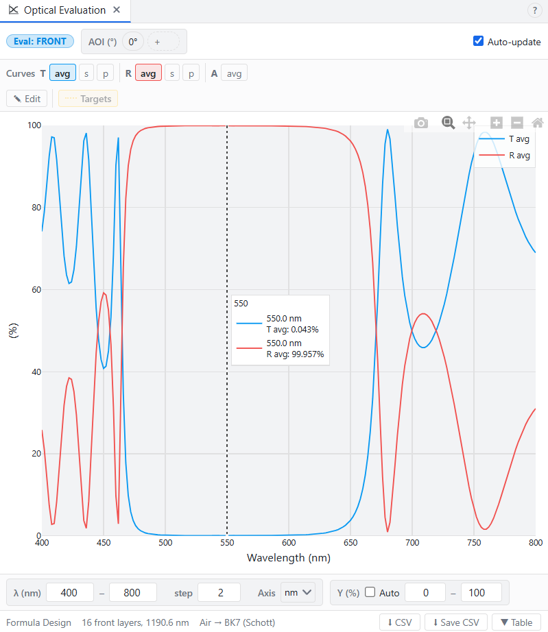
Two quick changes show how the structure behaves:
- Open Formula window again and change the formula to
(HL)^4, click Replace. The mirror now has fewer layers and lower peak reflectance.
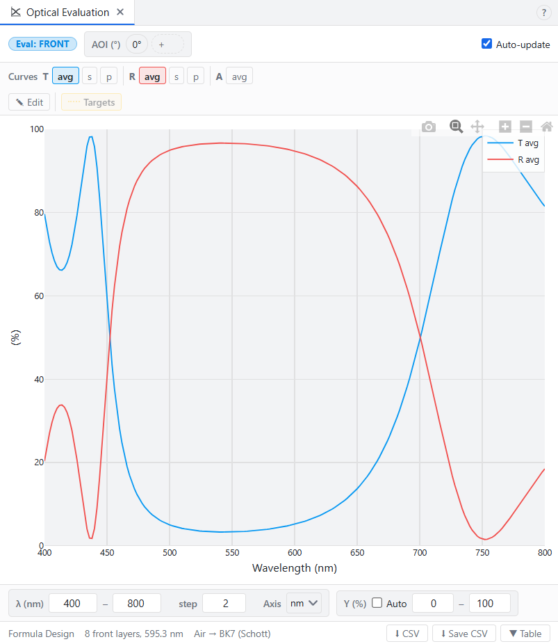
- Restore
(HL)^8and change reference to 800 nm either in Stack Formula or in Design Editor. Now the high-reflectance band moved to the right as physical thicknesses of layers were automatically recalculated to new reference wavelength.
That is the basic dielectric mirror.