 TFStudio
 How to Design an Antireflection (AR) Coating: A Step-by-Step Guide
Design a single-layer antireflection coating for glass, derive the quarter-wave conditions, and verify the result in TFStudio.
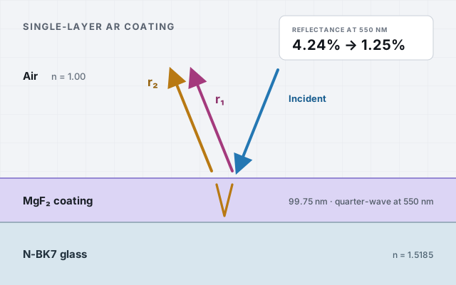
Every air-glass surface reflects about 4% of the light that hits it. In a system with several lenses, those reflections reduce transmission and produce ghost images and glare. The simplest useful antireflection (AR) coating is a single thin layer.
This guide derives the quarter-wave design conditions, works through the numbers, and then verifies the result in TFStudio.
Why a bare surface reflects 4%
When light crosses a boundary between two media, some of it reflects. At normal incidence the fraction reflected from a single surface is
At 550 nm, TFStudio's material library uses for air and for N-BK7:
That is per surface. A lens has two, so roughly 8% of your light is gone.
The idea: cancel reflection with interference
A single-layer AR coating adds one transparent film on top of the glass. Now there are two reflecting surfaces: air-film and film-glass. If we choose the film's thickness so the two reflected waves come back exactly out of step, they cancel. If we also choose the film's index so the two reflections are equal in strength, the cancellation is complete.
Condition 1: thickness (a quarter wave).
The film must be one quarter of a wavelength thick optically, so the round trip through it delays the second reflection by half a wave:
Condition 2: index (the geometric mean).
For the two reflections to be equal in amplitude, the film index must be the geometric mean of the media on either side:
This is the classic quarter-wave result: a quarter-wave film of admittance transforms the substrate so the front surface sees the incident medium exactly.
Calculations
Using the same N-BK7 value, the ideal film index is
Here is the catch that makes AR design a real engineering problem: no durable solid material has an index that low. The closest practical, hard, stable coating material is magnesium fluoride, MgF₂. TFStudio's library gives at 550 nm.
So we accept the compromise. With MgF₂ the reflection at the design wavelength does not reach zero, but it drops dramatically:
From 4.24% down to roughly 1.25% per surface, with one layer. This is why MgF₂ has been a workhorse material for consumer optics: it is inexpensive, durable, and effective.
Design at the center of the visible band, . The physical thickness is
That's the whole design: 99.75 nm of MgF₂ on N-BK7. Now let's verify it.
Building it in TFStudio
Open the web demo or install Windows release from github repository.
1. Set up
- Substrate: N-BK7 ( at 550 nm)
- Incident medium: Air
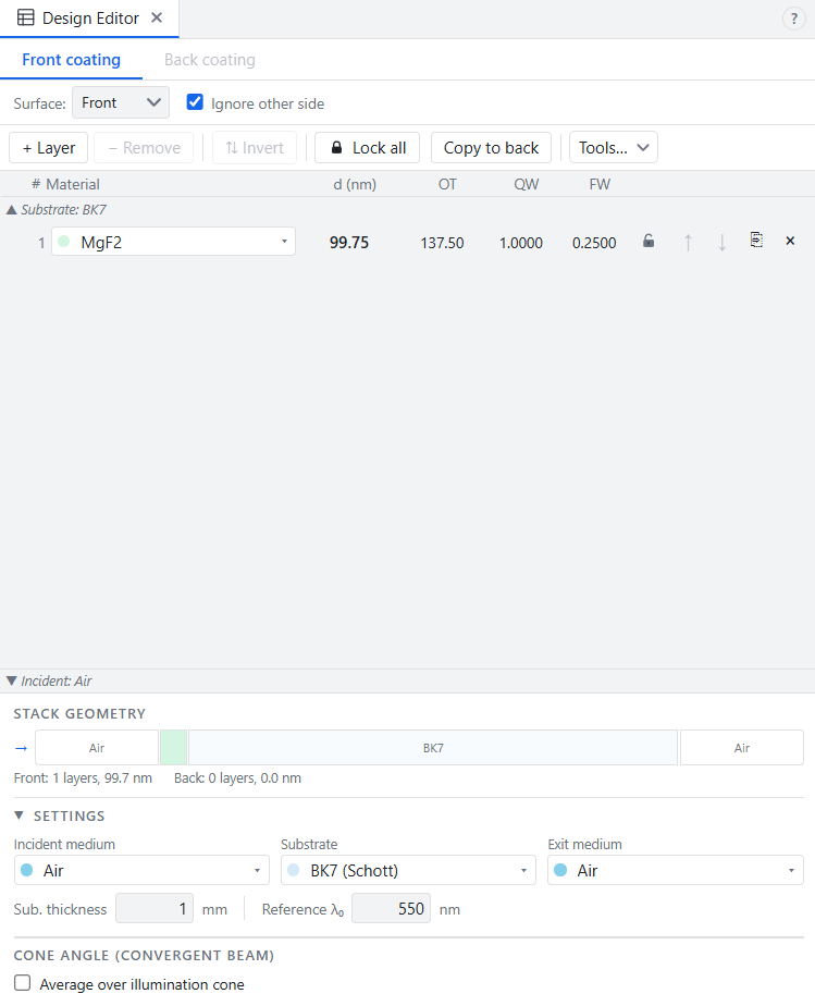
- Add one layer: MgF₂ ( at 550 nm).
- Set its optical thickness to 1 quarter-wave at 550 nm. TFStudio converts that to 99.75 nm.
2. Plot the reflectance
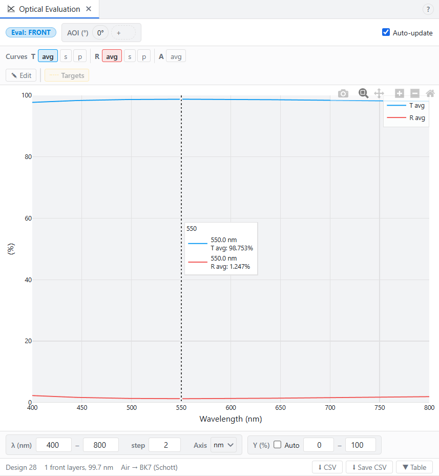
Open the optical evaluation plot over 400–800 nm. You will see a smooth nearly flat reflectance curve that dips to about 1.25% near 550 nm.
3. Compare against bare glass
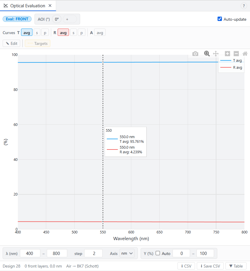
Remove that layer again and watch the curve jump up to 4.24% at 550 nm.
Cons
The single layer is useful, but it only reaches roughly 1.25%, not zero, because MgF₂ has an index of 1.3785 rather than the ideal 1.2323. A two-layer V-coat can get much closer to zero at one wavelength by using two materials.
Recap
- A bare N-BK7 surface in air reflects roughly 4.24% at 550 nm.
- A single quarter-wave film cancels reflection by interference; ideal index is and thickness is .
- For N-BK7, the ideal index is 1.2323; MgF₂ () gets you to
approximately 1.25%.