 TFStudio
 Taking a Coating from TFStudio into Zemax OpticStudio
Export a four-layer AR design as COATING.DAT, apply it to a glass plate in OpticStudio, and check that both programs agree on the spectrum.
A coating design is rarely the end of the job. It has to reach the lens designer, and it usually reaches them as a table of thicknesses in an email, which somebody then retypes into OpticStudio.
This tutorial does the handoff properly. We export the refined four-layer AR coating from the broadband AR tutorial as a COATING.DAT file, apply it to one face of a glass plate in OpticStudio, and then compare the transmission both programs predict for that plate.
The design being exported
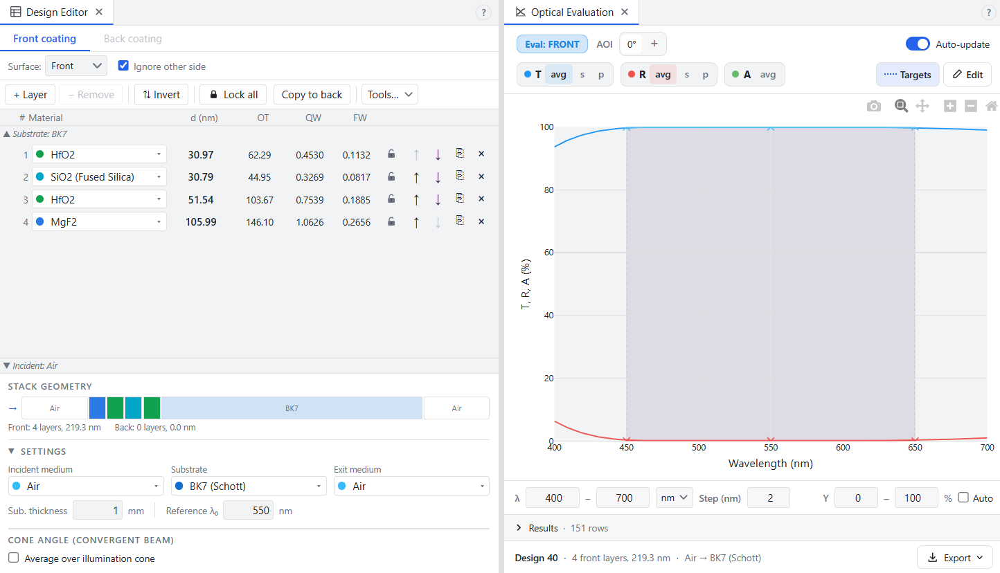
The refined stack from the earlier tutorial, as the Design Editor shows it, substrate-adjacent layer first:
| Design Editor layer | Material | Thickness |
|---|---|---|
| 1 | HfO2 |
30.97 nm |
| 2 | SiO2 (Fused Silica) |
30.79 nm |
| 3 | HfO2 |
51.54 nm |
| 4 | MgF2 |
105.99 nm |
Substrate BK7 (Schott), incident medium Air, reference wavelength 550 nm. Over 450 to 650 nm the coated surface reflects 0.08% on average.
 ---
---
Export the file

Open Data Exchange → Zemax and select the Export tab. Four settings control what gets written.
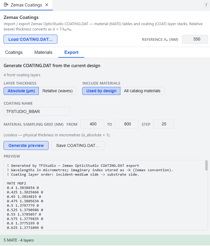
Layer thickness. Absolute (µm) writes the physical thickness of each layer directly. Relative (waves) writes optical thickness in waves of the reference wavelength, which is what Zemax itself uses by default. Absolute is the safer choice and it is what we use here, for a reason covered below.
Include materials. Used by design writes only the materials this coating needs. All writes every material in your loaded catalogs, which produces a large file but gives the recipient a library they can reuse. Use Used by design unless you are deliberately shipping a catalog.
Coating name. The name OpticStudio will list. Keep it short and free of spaces.
Material sampling grid. Zemax stores dispersion as a table and interpolates linearly between the points, so this grid is the resolution at which OpticStudio will see your materials. Sample more finely if a material has structure in it, and always sample at least the full range of your analysis, because Zemax clamps at the ends of the table rather than extrapolating.
Click Generate to fill the preview, then Save.
What the file says
The output is plain text, and it is worth reading once rather than trusting blindly.
! Generated by TFStudio — Zemax OpticStudio COATING.DAT export
! Wavelengths in micrometres; imaginary index stored as -k (Zemax convention).
! Coating layer order: incident-medium side -> substrate side.

MATE MGF2
0.4 1.3838654 0
0.425 1.3825666 0
0.45 1.3814815 0
0.475 1.3805634 0
0.5 1.3797779 0
0.525 1.3790986 0
0.55 1.3785057 0
0.575 1.3779835 0
0.6 1.3775199 0
0.625 1.3771049 0
0.65 1.3767309 0
0.675 1.3763913 0
0.7 1.376081 0
0.725 1.3757957 0
0.75 1.3755316 0
0.775 1.375286 0
0.8 1.3750561 0

MATE HFO2
0.4 2.0603611 -0.0000011315421
0.425 2.0485867 -0.0000013651206
0.45 2.0387134 -0.0000016284784
0.475 2.0302062 -0.0000019228166
0.5 2.0229494 -0.0000022503472
0.525 2.0166967 -0.0000026133033
0.55 2.0112385 -0.0000030133568
0.575 2.0064525 -0.0000034517763
0.6 2.0022345 -0.0000039304387
0.625 1.9984945 -0.0000044509562
0.65 1.9951387 -0.0000050144126
0.675 1.9921614 -0.000005625365
0.7 1.9894129 -0.0000062821769
0.725 1.9870392 -0.0000069884926
0.75 1.9847777 -0.000007746669
0.775 1.9827738 -0.0000085563014
0.8 1.9808841 -0.0000094203194

MATE SIO2__FUSED_SILICA_
0.4 1.4701161 0
0.425 1.4676339 0
0.45 1.4655657 0
0.475 1.4638192 0
0.5 1.4623265 0
0.525 1.4610367 0
0.55 1.4599109 0
0.575 1.4589191 0
0.6 1.4580377 0
0.625 1.457248 0
0.65 1.456535 0
0.675 1.4558864 0
0.7 1.4552925 0
0.725 1.4547448 0
0.75 1.4542367 0
0.775 1.4537625 0
0.8 1.4533173 0

COAT TFSTUDIO_BBAR
MGF2 0.10598526 1
HFO2 0.05154384 1
SIO2__FUSED_SILICA_ 0.030786233 1
HFO2 0.030968653 1
The imaginary index is negative. TFStudio, like most of the thin-film literature, writes the complex index as with . Zemax stores the imaginary part with the opposite sign.
The trailing 1 is the thickness flag. In a COAT line, is_absolute = 1 means the number before it is a physical thickness in micrometres. is_absolute = 0 means it is an optical thickness in waves of the lens primary wavelength , and the physical thickness is then
where is the real index of that layer at .
The layer order is reversed relative to the Design Editor. The COAT block runs from the incident medium toward the substrate, so MGF2 comes first. The Design Editor lists the substrate-adjacent layer first.
Names. Zemax names are at most 32 characters with no spaces or punctuation, so SiO2 (Fused Silica) becomes SIO2__FUSED_SILICA_.
Load it into OpticStudio
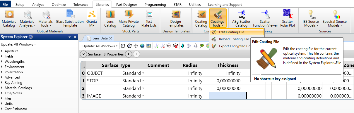
Then you can copy COATING.DAT into the coating folder of your OpticStudio data directory which usually is C:\Users\user_name\Documents\Zemax\Coatings. Or you can copy all strings from the preview and insert them in your own COATING.DAT which you can edit from Libraries → Coating Tools → Edit coating file:
Make a plane-parallel plate:
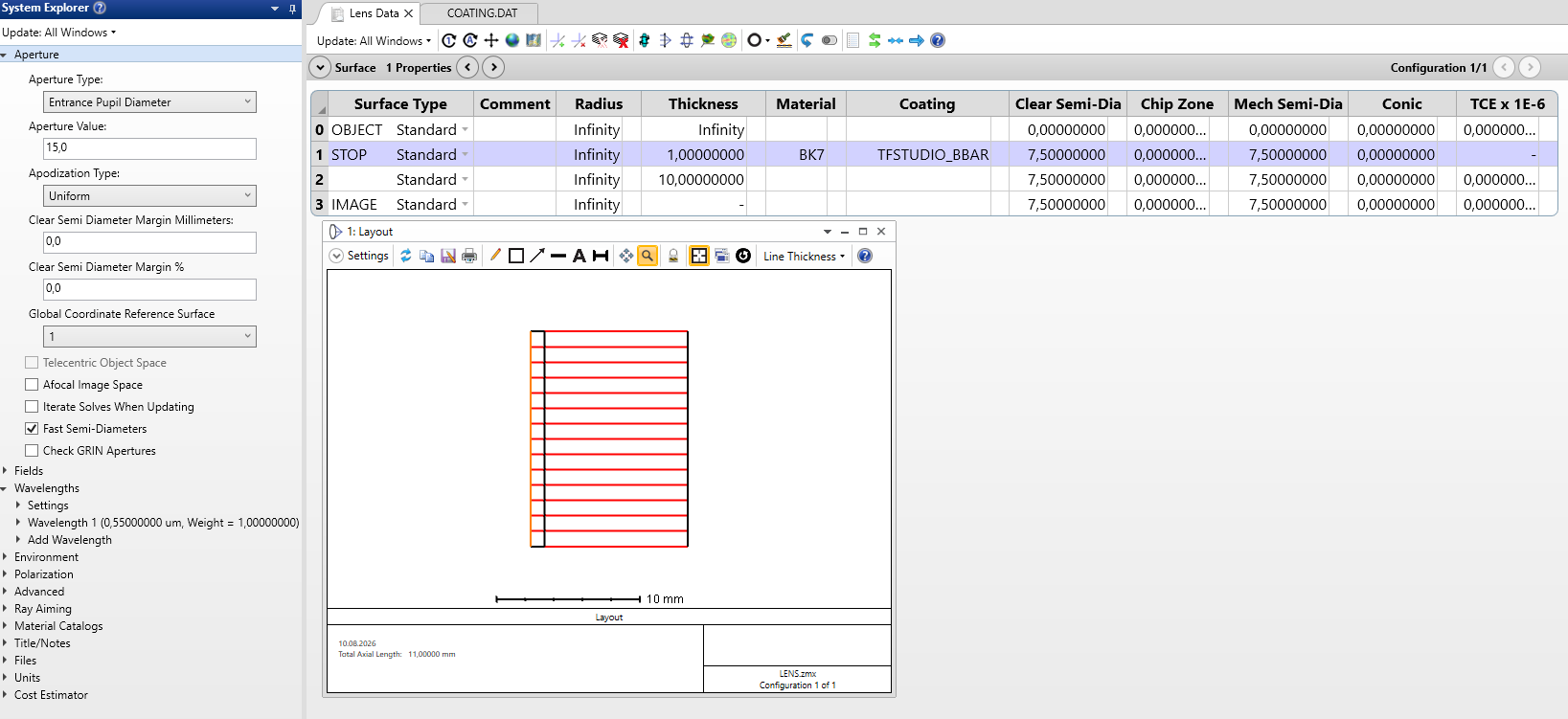
- A Standard surface with the BK7 glass, thickness 1 millimeter.
- A second Standard surface.
- Set aperture, for example Entrance pupil diameter
Set the Coating cell of the first surface to your coating name and leave the second surface bare. One coated face and one uncoated face.
Now you'll have something like this:
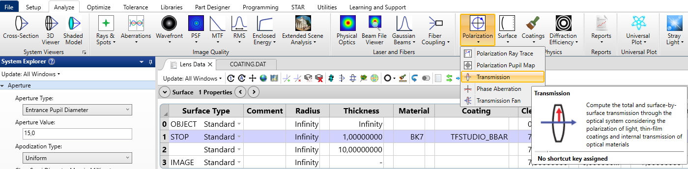
Now open Analyze → Polarization → Transmission.
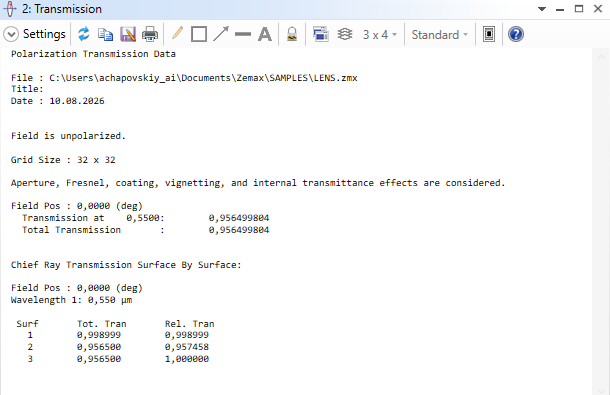
Field Pos : 0,0000 (deg)
  Transmission at    0,5500:	    0,956499804
  Total Transmission       :	    0,956499804

Chief Ray Transmission Surface By Surface:

Field Pos : 0,0000 (deg)
Wavelength 1: 0,550 µm

 Surf    	Tot. Tran    	Rel. Tran
   1 	    0,998999 	    0,998999
   2 	    0,956500 	    0,957458
   3 	    0,956500 	    1,000000
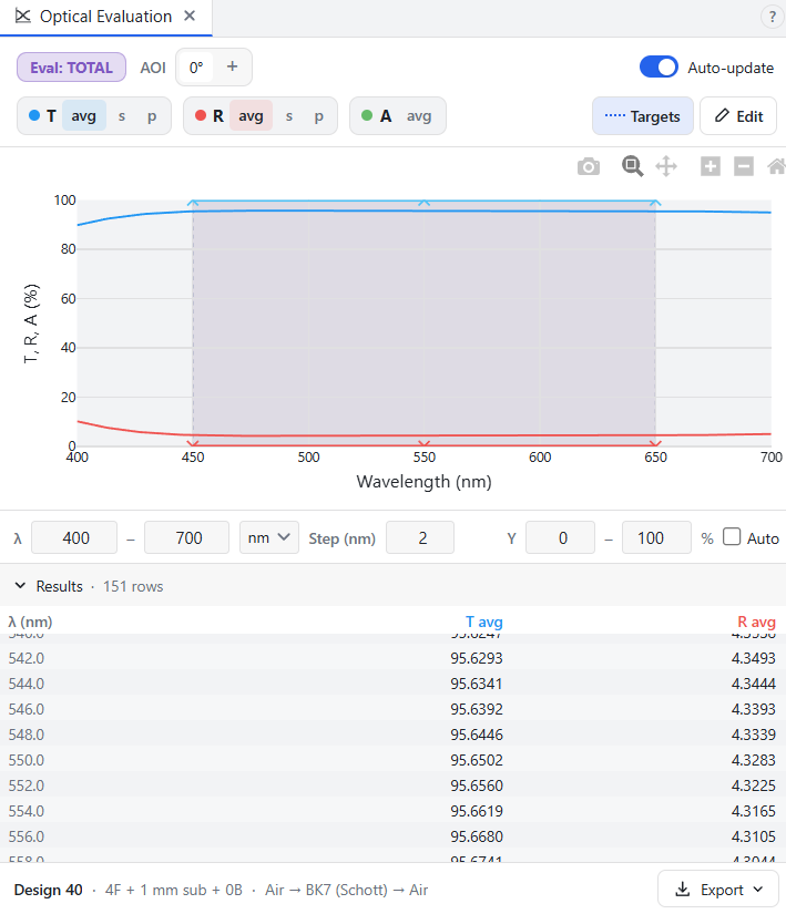
Zemax calculated total transmission 95.6499% for this glass plate. Checking TFStudio result in Optical Evaluation with Ignore other side unchecked in Design Editor I got 95.6502%.
Agreement on results
The two numbers differ by 0.0002%. Two effects make up those last digits, and they almost cancel.
Multiple reflections, worth +0.0040%. Sequential Zemax does not account for light bouncing between the two faces of the plate, and its own listing shows it: , the plain product of the two surfaces. TFStudio sums the series,
where is the single-pass transmittance of the glass. With the coating on, and , so the correction is a factor 1.000042.
Substrate absorption, worth −0.0038%. Schott publishes N-BK7 internal transmittance for two sample thicknesses, 10 mm and 25 mm. Both programs derive the substrate extinction coefficient from that data, but TFStudio uses the 10 mm column and Zemax's glass catalog carries the 25 mm one, so the two end up with slightly different : against at 550 nm. TFStudio absorbs marginally more, which cancels most of the reflection term above.
The useful conclusion is not that the programs agree. It is that at this level the interference calculation has stopped being the limiting factor and the glass transmission data has taken over. If you ever chase a disagreement smaller than about 0.01% between two coating programs, check the material data first, and check which sample thickness it came from.
From Zemax to TFStudio
Vendors may ship coating libraries as COATING.DAT, and those files contain real measured dispersion. Open the Coatings tab, load a file, and TFStudio registers its materials as a catalog named after the file, for example Zemax COATING. The negative imaginary indices come back as , relative thicknesses are converted to physical nanometres using the you supply, and the layer stack lands in the Design Editor in the order TFStudio expects.
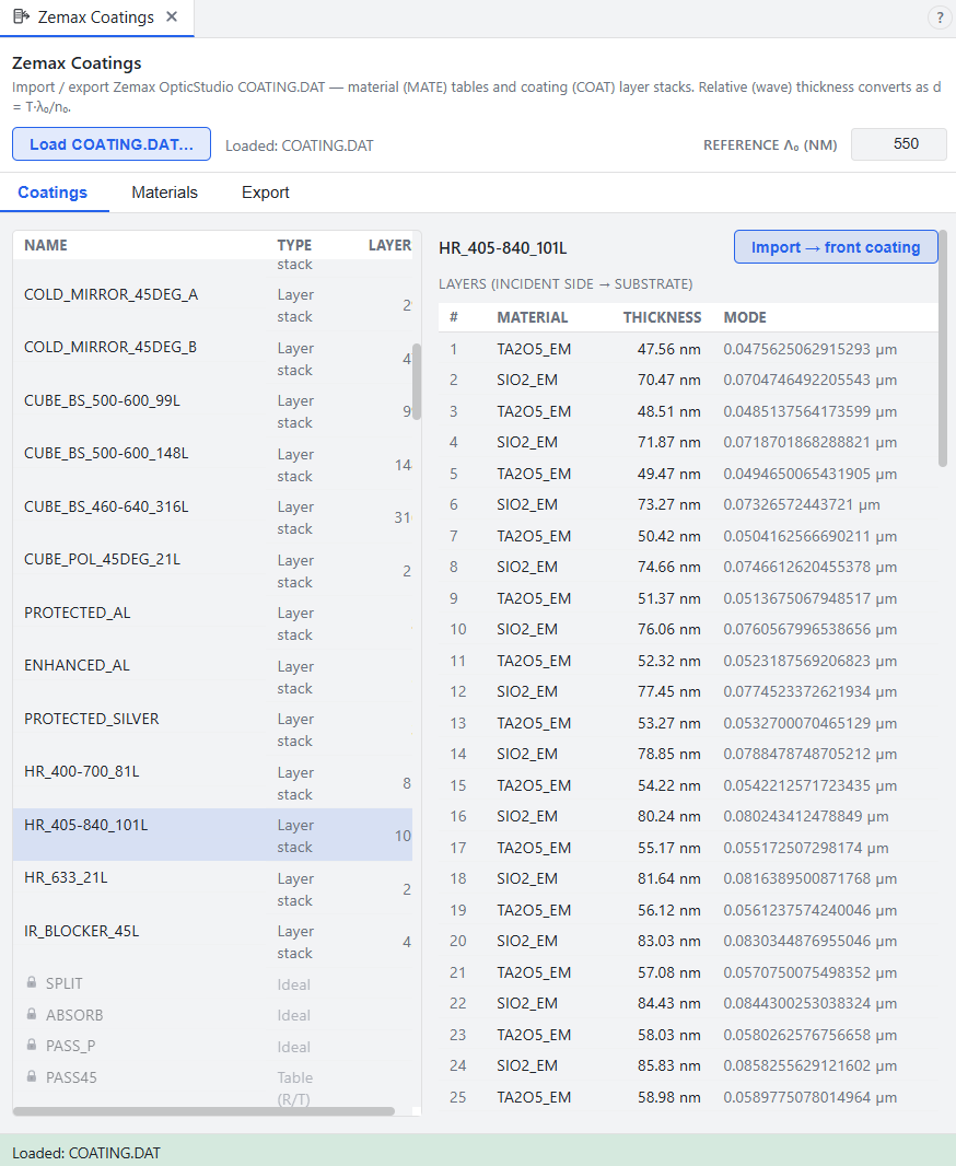
Plain layer stacks import as designs. The other things a coating file can hold, ideal coatings with a fixed transmission, tabulated angle-and-wavelength data, and tapered or encrypted coatings, are parsed and listed so you can see what is in the file, but they cannot be imported.
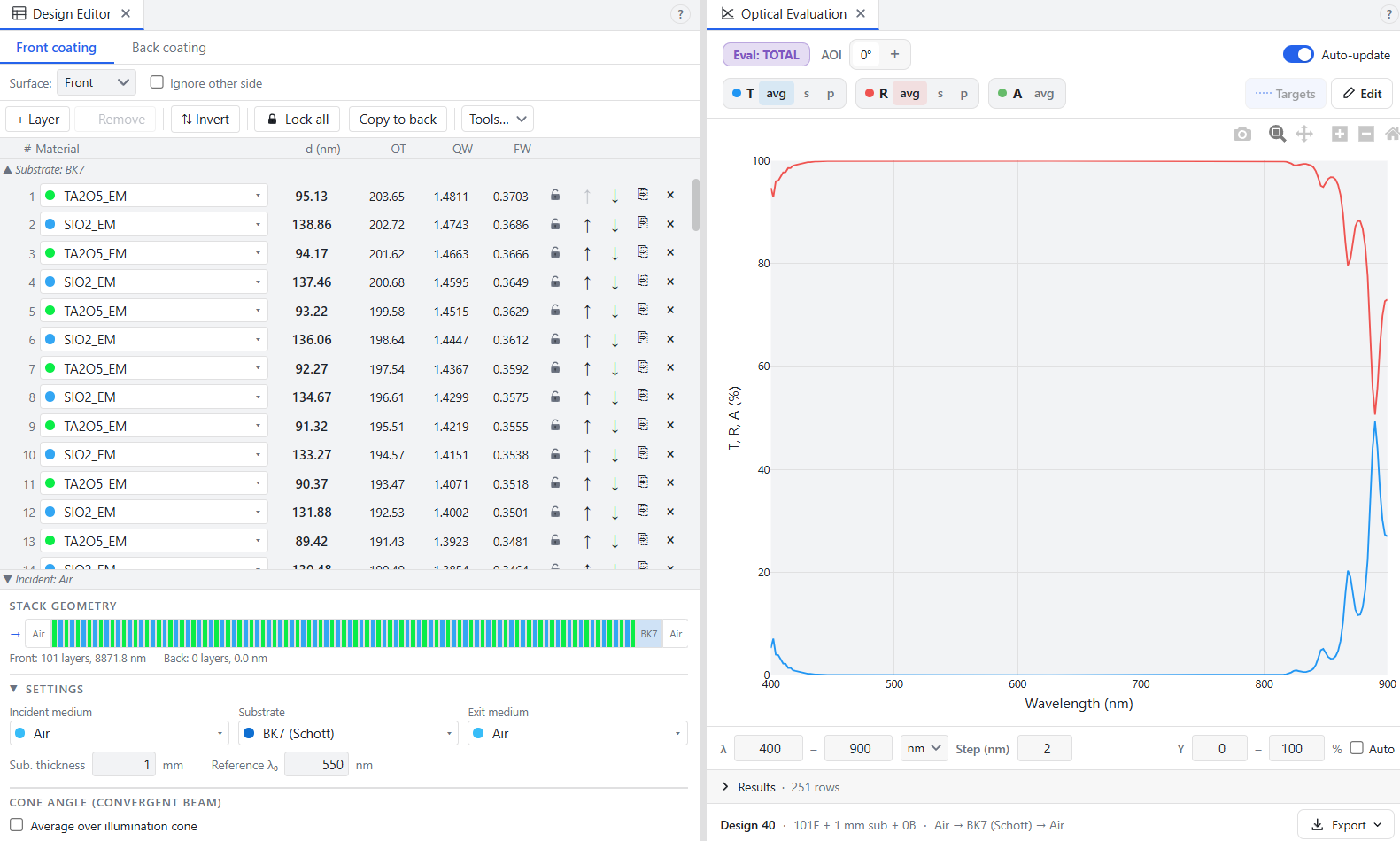
Here I imported dielectric mirror coating HR_405-840_101L that came with my default COATING.DAT file: